

PROTOTYPES
This pages shows the various prototypes made to help inform me of design decisions. These include physical models and CAD models.

SPACE MODEL
This model was a very basic model to give a the Foot Pedal a 3D presence as it had only been scale models previously. This model showed me that the pedal sizing was slightly too small and needed adjusting. However through feeback it was shown that the angle and heigh of the pedal was comofortable.

RACK AND PINION MODELS
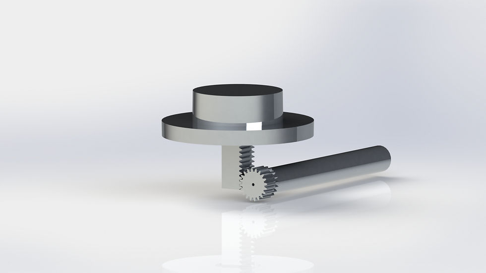
As shown in the Other Data page, a Rack and Pinion mechanism was most suitable method to reduce the lenght of the spring; thus increasing the users difficulty to push down a pedal.
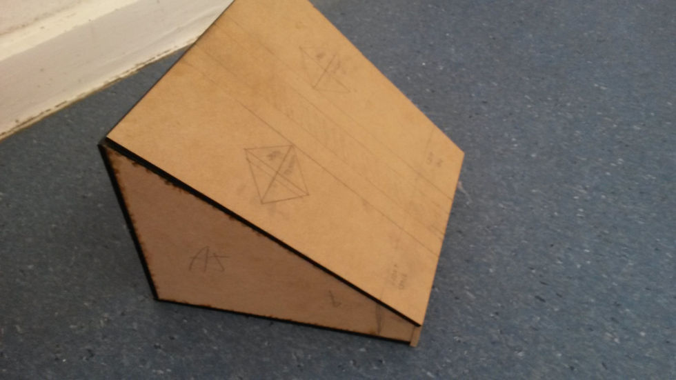
Laser cutting out a Rack and Pinion gave me an understanding of how the components should interact and also raised problems such as how long will the Rack be in order to decrease the spring length sufficiently, and how would this be supported inside the product.
Through the use of CAD modelling it became apparent that due to such a small space available that the adjustable length of the Rack would be so small that it would effectively have no use.


PLUNGER
Using Solidworks to create a full scale model, the plunger device that would be located inside the springs internal diameter was 3D printed.
This gave the object a 3D presence and also allowed me to slightly adjust the height and width of the female part.
This plunger idea was based around how a medical syringe works. As the female plunger part is pushed down under the force of the pedal, not only does it act as a stabiliser to stop any sideways and jittery movement but it also makes it the pedal harder for the user to push down as it becomes more compressed.

WORKS LIKE MODEL
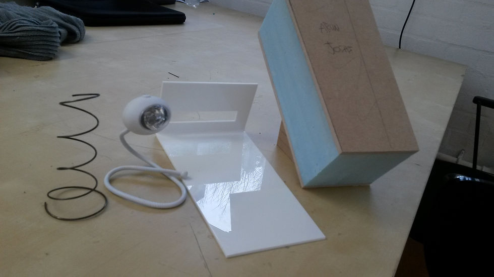
This model was made simulate the movement of the pedal. This was achieved by taking the spring out of an existing foot pedal firstly (note, this spring was not the correct length or spring rate, as buying the correct springs in would have been too expensive).
The spring was attached to a wooden block that was at the same angle (35 degrees) as the pedals should be. This was then stuck down using a glue gun.
To make the pedal, a net was cut out on the laser cutter using 3mm white acrylic. This acrylic was then line bent on the edge of the net in order to create the shape of the pedal. The net had large face to stop any sideways movement.
The spring was then glued to the pedal and a light was placed behind the pedal to give the illusion that it was lighting up.


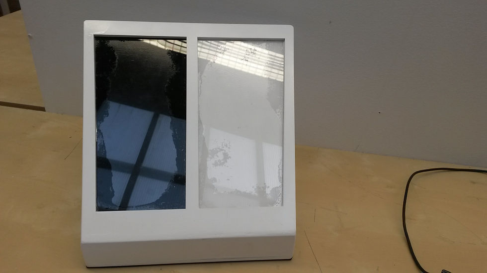
LOOKS LIKE MODEL
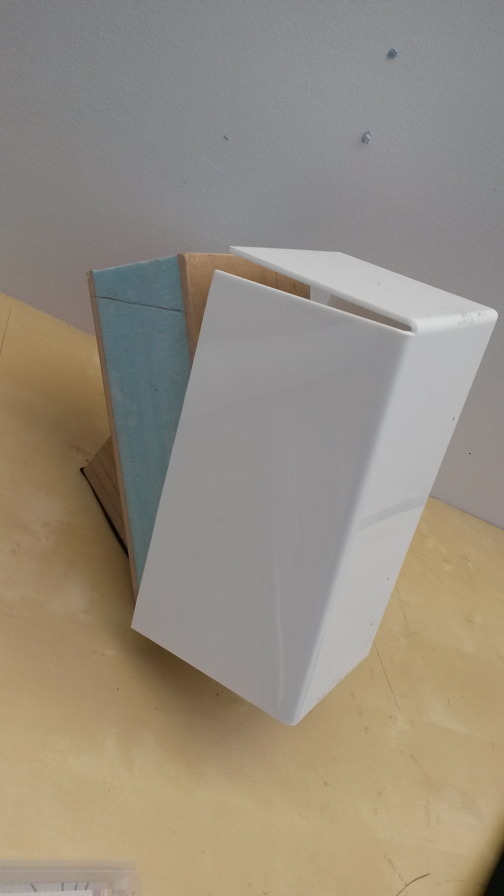
This model was made to show how the final Foot Pedal would look. It was created by cutting out the 6 faces on the laser cutter on 4mm MDF. These where then stuck together (minus the lid) to form the basic shape of the pedal.
Oversized pedals of 4mm MDF and clear 3mm acrylic where also cut out on the laser cutter. One of the pedals was then sprayed white and the other black. When they were dried the acrylic was then stuck over the top of this to give the translucent effect. These pedals were then stuck on the inside of the lid.
With the completed lid, the pedal was then stuck together to give the full shape. Filler was then used to produce filleted edges. Once this had been sanded down, primer and then white paint were applied.


REMOTE CONTROL MODEL
This model was made to simply show how the Foot Pedals and Central Hub System would be controlled.
The remote was created on Solidworks and was then 3D printed. The printed model was then smoothed using Wet and Dry paper. It was then primed and painted white.
The buttons were then painted seperatley to get a model as close to te original CAD as possible.